Figure template · System & Network · 4:3
Closed-Loop Brain–Computer Interface from Implant to Decoder
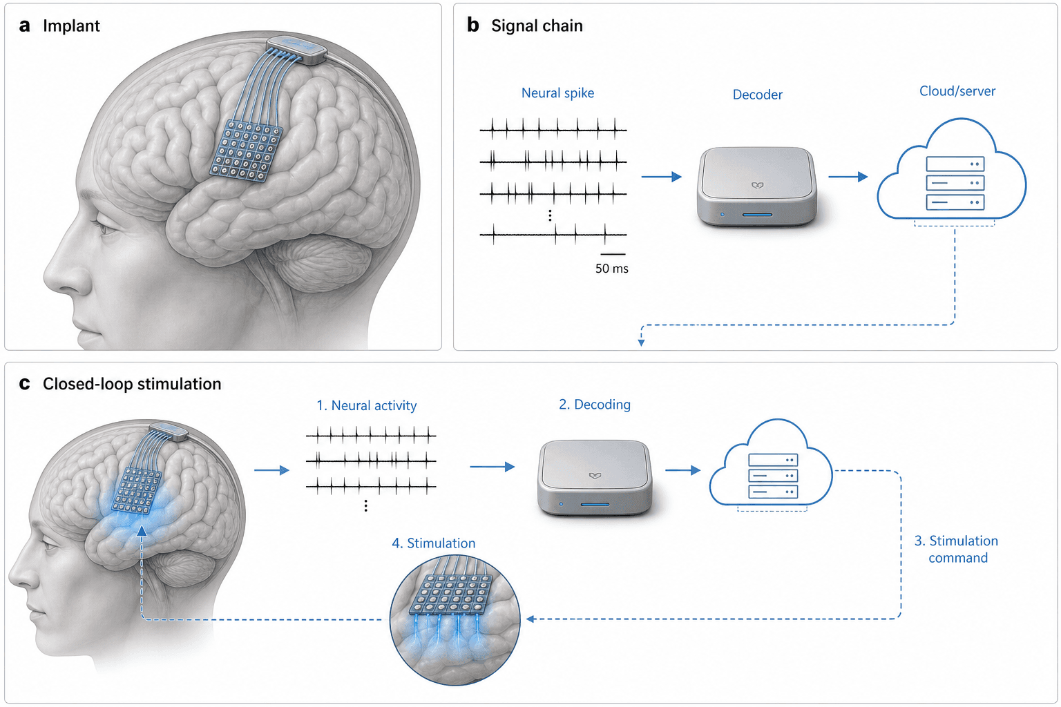
Three panels walk through a closed-loop brain–computer interface: an electrode array on the cortex, a signal chain from spikes to a decoder and server, and a numbered loop that turns decoded activity back into stimulation of the brain.
Prompt
Create a scientific figure about: Closed-loop brain–computer interface from implant to decoder. Visual style: Clean Vector. Requirements: publication-ready scientific quality, clear labels and directional arrows where appropriate, avoid cartoon or stock-photo look, composition optimized for research papers and academic slides.
What this template is
Panel a shows a translucent head in profile with a square electrode array on the cortical surface and fine leads running to a connector on the skull. Panel b lines up several spike trains, then a boxed decoder, then a cloud server, with a dashed line dropping into panel c. Panel c bends the same chain into a loop: step one records neural activity, step two decodes it, step three issues a stimulation command, and step four delivers current from the array in a circular close-up, with a dashed arrow back to the brain. Readers should understand how recording, decoding and stimulation form a single feedback loop.
Elements to label
Cortical electrode array
The square grid on the cortex in panel a; state whether it is a surface grid or penetrating microelectrodes.
Skull connector
Leads gather at a box on the skull; note whether the data leave by cable or through a wireless link.
Spike trains
Rows of vertical ticks for spikes; the scale bar value is a placeholder, so use your recording's own time scale.
Decoder
The silver box labelled Decoder; name the algorithm, such as a Kalman filter or a recurrent neural network.
Cloud server
Server racks inside a cloud outline; say whether it trains models, stores data or computes in real time.
Numbered loop
Four steps from activity to stimulation in panel c; rename them after your actual processing stages.
Stimulation close-up
The circular inset where the array sends blue current downward; note the stimulation parameter type, such as pulse width.
Return arrow
A dashed arrow carries stimulation back to the brain in panel c; label the target region it reaches.
Where it is used
- Paper mechanism figure
- Grant proposal
- Defense slides
- Graphical abstract
What reviewers look for
Loop latency
Routing signals through a cloud server and back could exceed the delay a closed loop tolerates. Reviewers will ask where real-time decoding runs and will expect an end-to-end latency figure for the whole loop.
Recording and stimulating on one array
The same array both records and stimulates. Expect questions about how stimulation artefacts are removed and whether recording and stimulation are separated in time or assigned to different electrodes. Show which.
Electrode type versus signal
A surface grid usually picks up field potentials, yet the traces show single-unit spikes. Make the electrode type and the signal agree, and name the brain region the array is placed over.
Safety
Chronic implants raise tissue response, charge-injection limits and infection risk. Papers that include stimulation generally report safety parameters in the caption or main text, and reviewers check for them.
How to use it in Yila
- 1Pick a figure
- 2Describe your subject and the steps to stress
- 3Refine it in chat, then download the PNG
Tips
Do
- State whether decoding runs on the implant, a local device or the cloud, so the chain matches your system.
- Ask for each loop step in panel c to name its operation, such as feature extraction or waveform choice.
- Request your experimental animal, such as a macaque or rat, with the array moved to the right region.
Avoid
- Keeping the sample scale-bar value, which comes from no real recording and will mislead readers.
- Repeating the same decoder and server in panels b and c when space is tight; merge them into one panel.
- Showing the brain through a transparent head without saying so; a short caption note avoids confusion.
Questions
Can this closed-loop BCI figure go straight into a paper?
Treat it as a draft system overview. It is AI-generated, so electrode placement, signal shapes and the scale bar are not your data. Substitute the real brain region and recording parameters, remove the placeholder scale bar and state where decoding happens before the figure goes into a manuscript.
Can I change the array or one step of the chain?
Individual parts cannot be selected and edited, and the image is not a vector graphic. Ask in a Yila chat, for instance replacing the cloud with an implanted chip or the surface grid with penetrating electrodes, and the whole figure is regenerated with the same panel layout. Describe one change at a time.
What format do I get?
An AI-generated PNG in landscape with three panels labelled a, b and c. If a journal requires vector or layered files, redraw the layout in illustration software using this as a guide, and keep the panel letters where readers expect them.
Do I need to pay?
Browsing this page and the sample costs nothing. Generating and editing figures in Yila consumes credits, and new users are given 2,500 credits at sign-up, which is enough to try several versions before settling on one. Viewing samples never uses credits.
My work is decoding for a robotic arm, with no stimulation. Can the figure adapt?
Yes. Replace the stimulation step with an external effector, such as a robotic arm or a cursor, and say whether sensory feedback stays in the loop. Yila redraws panel c accordingly, and panel b can keep the same decoder. Name the effector's controller if relevant.
Can electrical stimulation be swapped for optogenetics?
Yes. Give the light source, the opsin and the brain region that expresses it, and Yila turns the stimulation close-up into an optical fibre or micro-LED. The recording side can switch to calcium imaging at the same time so the loop matches your experiment.