Figure template · Lab Apparatus · 4:3
Organ-on-Chip Flow Path and Membrane Figure
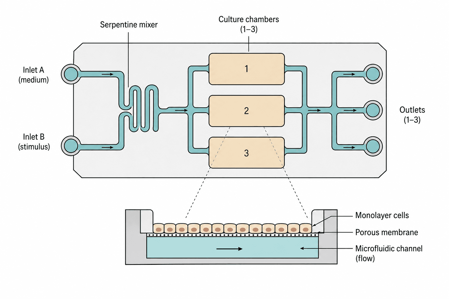
A top view of the chip carries two inlets through a serpentine mixer and splits the stream across three numbered culture chambers, while a cutaway below opens one chamber to show cells on a porous membrane above a flowing channel.
Prompt
Create a scientific figure about: Organ-on-chip with mixer, culture chambers, and membrane flow. Visual style: Clean Vector. Requirements: publication-ready scientific quality, clear labels and directional arrows where appropriate, avoid cartoon or stock-photo look, composition optimized for research papers and academic slides.
What this template is
The figure shows one chip from two viewpoints. The top view carries the fluidics: where each stream enters, where the two combine, which chambers they pass and where they leave. The cutaway supplies the vertical arrangement a top view cannot show, with a monolayer sitting on the upper face of a porous membrane and a channel beneath it under continuous flow, so exchange happens across the membrane rather than along the chamber. A reader should be able to state what each inlet carries, whether the chambers are parallel or in series, and which side of the membrane the cells feel the flow from.
Elements to label
Two inlets
Round ports on the left, one for medium and one for the stimulus, each with an arrow pointing into the chip.
Serpentine mixer
The folded channel where the two streams meet, labelled as the mixer, with its turn count given in the caption.
Split and chambers
Three numbered rounded chambers in a column, fed and drained symmetrically, which marks them as parallel.
Outlets
Three ports on the right, one per chamber, arrows facing outward and labels naming what is collected.
Cutaway leaders
Two dashed lines run from the middle chamber down to the section, showing which chamber was opened.
Monolayer and membrane
Columnar cells packed side by side on top of a thin dotted line standing for the porous membrane.
Channel beneath
The filled channel under the membrane with a horizontal arrow for flow direction and chip walls at both ends.
Section labels
Three lines of text at the right of the cutaway point to the monolayer, the membrane and the channel.
Where it is used
- Paper mechanism figure
- Defense slides
- Academic poster
- Course handout
What reviewers look for
Is the flow really split evenly
All three chambers branch off one channel of equal drawn width, but real resistance depends on length and cross-section. Unless you measured the split, do not let the drawing imply the chambers are identical.
Does the mixer mix
A few serpentine turns mix by diffusion alone under laminar flow, and whether that suffices depends on flow rate and channel size. Reviewers do ask about mixing efficiency, so support the claim in the caption.
Which side carries cells
In the cutaway all cells sit above the membrane with only fluid below. If your model seeds a second cell type on the underside, it has to be drawn, or the figure contradicts the methods.
No scale anywhere
Nothing states whether a chamber is millimetres or centimetres across, and the membrane pore size is not given either. Add at least a scale bar to the cutaway, and ideally the chamber footprint as well.
How to use it in Yila
- 1Pick a figure
- 2Describe your subject and the steps to stress
- 3Refine it in chat, then download the PNG
Tips
Do
- Name the actual fluid in each inlet label instead of A and B, so the design intent is readable at a glance.
- Give the cutaway a scale bar and a pore size; reviewers judge the model's plausibility from those two first.
- If the three chambers hold different cell types, colour them separately and say so in the legend.
Avoid
- Do not route the cutaway leaders across the other chambers; take them straight down from the opened chamber's edge.
- Do not draw the membrane as a solid line, or readers assume the two sides are sealed off from each other.
Questions
Can this go straight into a paper?
It works as a first draft of the device schematic. It is an AI-generated raster image, so before submission add dimensions and a pore size, confirm which side of the membrane your cells occupy, check that the flow path matches the chip you actually built, and refine line weights in Yila.
Can elements in the figure be changed?
Not element by element, but you can keep refining it by chatting in Yila: change the chamber count, add a recirculation loop, seed a second cell layer under the membrane, or keep only the cutaway, then generate a new version from that description.
What format is delivered?
An AI-generated PNG image in a 4:3 landscape layout. It is not a vector graphic, so the narrow channels and the membrane pores soften once the figure is reduced; check it at the size it will occupy in a methods section or on a poster.
Is it free?
Viewing this page and the sample costs nothing. Generating a version in Yila consumes credits, and a new account receives 2,500 credits, which is enough to bring the flow path, the chamber count and the cutaway detail into line with your own chip.
My chip has one channel, not three chambers. Can it be adapted?
Yes. Tell Yila how many chambers you have and how they connect, and the top view simplifies while the cutaway stays as it is. For a series design, also ask for the split to become an end-to-end path with the outlets merged into one.
Can I keep only the cutaway?
Ask for the chamber section alone, without the top view and its leader lines. On its own it explains the relationship between the cells and the flow more directly, and the labels can be set larger for a handout or a slide.