Figure template · Lab Apparatus · 4:3
UHPLC System Instrument Schematic
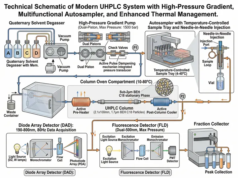
A landscape flow schematic laid out in six stages, from solvent reservoirs and degassing through the pump, injector, column oven and detectors to fraction collection, with cutaways for the pump head and the injection valve.
Prompt
Create a scientific figure about: Modern UHPLC system with degasser, high-pressure pump, autosampler, column oven, and detector. Visual style: Clean Vector. Requirements: publication-ready scientific quality, clear labels and directional arrows where appropriate, avoid cartoon or stock-photo look, composition optimized for research papers and academic slides.
What this template is
The schematic flattens a whole chromatograph into one traceable line. Four mobile phase bottles pass through in-line degassing into the pump, where twin pistons, check valves and a pulse damper steady the baseline. The autosampler draws from a thermostatted tray and the valve pushes the plug through the pre-heater into a column packed with sub-2 µm particles; after post-column cooling the eluent reaches the diode array detector, then the fluorescence detector, and finally the fraction collector or waste. A reader should be able to point at the segment carrying the highest back pressure.
Elements to label
Solvents and degassing
Letter each reservoir by channel and label the degasser once; a second vacuum pump drawing adds nothing.
Pump head cutaway
Open the twin pistons, check valves and pulse damper in a cutaway and point a leader at the pressure transducer.
Thermostatted autosampler
State the tray temperature range and place the needle and sample loop close-up beside it, naming the injection mode.
Column oven and heaters
Draw the oven as a transparent box, label the pre-heater and post-column cooler once each, and give the oven range.
Column and packing inset
Mark bore, length and particle size on the column body, and show packed spherical particles in the round inset.
Diode array detector
Chain lamp, monochromator, flow cell and array, with the wavelength range and acquisition rate written above.
Fluorescence light path
Excitation source, excitation monochromator, flow cell, emission monochromator and photomultiplier, each named separately.
Collection and waste
Split the end into a collector rack labelled as peak collection and a line running to the waste bottle.
Where it is used
- Paper mechanism figure
- Defense slides
- Course handout
- Lab website
What reviewers look for
Gradient type versus pump
Proportioning four solvents is low-pressure mixing, while a high-pressure gradient needs two independent pumps. The sample wires four bottles to one twin-piston pump and still calls it a high-pressure gradient; pick the one your instrument has.
Pressure rating sits on one part
The weakest of pump, fittings, column and flow cell sets the ceiling. The sample prints a rating on the pump and then repeats a pressure note beside the fluorescence detector, where it does not belong.
Back pressure belongs to the column
Sub-2 µm packing generates its pressure drop across the column itself, so place the two monitoring points to show that, or readers will credit the detectors. Label the monitoring points before and after the column.
One valve before the split
Waste and collection share the line until a switching valve divides them. The sample puts waste at the far left and the collector at the far right, which reads as two separate flow paths unless a valve is drawn.
How to use it in Yila
- 1Pick a figure
- 2Describe your subject and the steps to stress
- 3Refine it in chat, then download the PNG
Tips
Do
- Put your own column dimensions, oven temperature and detection wavelengths in the prompt so the labels carry real method values.
- Keep only the detectors you actually run; a single-detector system frees space to enlarge the column segment.
- Mark the two pressure monitoring points first, then the injection volume and flow rate; reviewers check those three.
Avoid
- Do not keep the misspelled component captions in the sample; an instrument diagram lives or dies by its labels.
- Do not allow the flow arrows to double back; one direction across the frame is what lets a reader count the stages.
- Do not leave two vacuum pump labels on one degasser; repeated captions make readers hunt for a second module.
Questions
Can this go straight into a paper?
Use it as a draft instrument schematic. Check every component name, every printed parameter and the direction of flow against your own system, then keep refining it in chat until the line weights and type size match the journal's figure rules.
Can elements in the figure be changed?
Not element by element, but you can keep refining it by chatting in Yila: turn the quaternary pump into a binary one, remove the fraction collector, replace fluorescence detection with a mass spectrometer interface, or add a column switching valve. Ask for one change per message so you can see what each edit did.
What format is delivered?
An AI-generated PNG in a 4:3 landscape frame, ready for a slide or a handout. It is not a vector graphic, so check that the small component captions survive the reduction before you place it in a two-column paper.
Is it free?
Browsing this page and viewing the sample cost nothing. Generating your own version in Yila consumes credits, and a new account starts with 2,500 credits, enough to rebuild the schematic around your own instrument over several rounds. Plan the edits you want before generating, since each new version draws on that balance.
Can I drop the cutaway insets?
Yes. Ask for the pump head and injection valve close-ups to be removed and only the main flow path with component outlines kept; the result spaces out and fits a narrow methods column better. The detector chain can also be stacked under the flow line there.
What about a version coupled to mass spectrometry?
Describe an ion source after the column, replace the fluorescence panel with the source and mass analyser, and keep the split to waste. The earlier stages stay in the same order across the frame. Keep the waste label visible.